Search This Blog

Friday, August 17, 2012

Pin Type Processors, and You: A Quick Guide to Replacing or Removing the Older PIN Style Processors from PowerEdge Servers, 8th Gen and Older

By Mike Kidd – Velocity Tech Solutions
One of the things I commonly find as a usual suspect in troubleshooting after replacing a system board is improperly seated or removed processors. Fret not, because this happens to the best of technicians and even the novice. In particular, when removing the processor from an 8th gen or older Dell server, the processor comes off with the heatsink. Not that this is always a problem, but it does greatly increase the chance of bending one of the thousands of tiny, tiny pins that make the unit work properly.
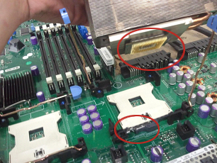
Notice the silver lever on the white processor socket is still down and the CPU itself is still attached to the heatsink. Some people assume that this is normal practice and attempt to remove the CPU from the heatsink and simply set it back on top of the processor socket without lifting that silver bar.

 Here is what the bar does:
The bar moves the socket forward, and what happens when the bar is up, it lets the CPU pins enter the socket straight up and down. Once the bar is moved back down, the socket shifts and locks the pins in place, creating the solid connection needed to run.

 So, you may be asking; how do I properly remove the heatsink and processor?

 If you look at my fantastic MS Paint skills, you will grab onto the heatsink and give it a twist. This will break the thermal compound free that attaches the processor to the heatsink. At first, it may seem kind of stiff and as if it is going to break. Don’t worry. As long as you twist instead of lift, the processor will stay safely in its socket until you raise the metal lever.


Hopefully this article will help you correctly remove your CPU and assist in motherboard replacement.
Feel free to call us at 888-784-2088 or visit our website anytime at www.velocitytechsolutions.com


Tuesday, April 17, 2012

How to Replace SAS 5 Controller on a PowerEdge Server

Today, we are going to do a quick write-up with a video on replacing a failed SAS 5 raid controller. This procedure is pretty much the same across the entire PowerEdge line of servers.
Firstly, shut down your server and open the case. Locate your SAS 5 raid controller and you will see something like Fig. 1.
Fig. 1
Unscrew the card from your case, and squeeze the blue tabs on the side of the SAS cable, lifting it straight off the card. Next, lift the card out of the server and replace it with your new one.
Installation is much more in-depth in the video demonstration, but basically is the reverse of the removal.
Now, when you turn your server back on, you will get a message stating your virtual disk is inactive/optimal. (Fig. 2)
We are going to go into the raid configuration utility by pressing “CTRL C” when prompted.
Fig. 2
Once inside, press “enter” and arrow over to the “raid properties” menu (Fig. 3) and press enter. We are going to arrow down to “manage array” (Fig. 4) and press enter. Now arrow down to “activate array” and press enter.
Fig 3
This part of the procedure can be a bit scary because it is taking the existing mirror and bringing it down to a raid 0 and re-syncing it back to a mirror or raid 1. As soon as you activate the array again, you will see it re-syncing if you go back into “manage array” (Fig. 4) in the configuration utility. I have seen windows while booting come up with “NTLDR NOT FOUND” until the sync is 100% complete so do not panic.
Fig 4
Don’t forget to check out the video to this article and our video tutorials at our YouTube channel: velocity783. Have a How-To request?  Request your own and we will get right to work on it for you!

Wednesday, March 28, 2012

How to clear an Idrac6


By Anne Tarantino Via Mike Kidd
I had a call from a customer unable to clear his Idrac6. Since in his case he had the BMC, Idrac6 Express and Idrac6 Enterprise, I had to get the big guns, the Kidd, Mike Kidd!
Mike took me through the 3 idracs on a Dell Poweredge R710 and for being not nearly as technical as he is , oddly it made sense to me.  The weird part to me was the clearing of Idrac6 which seemed a bit unconventional.  So often we joke about calling tech support and so often you hear “reboot” or “Unplug it” I will never ever again laugh at those commands from the tech on the other end of the line if I hadn’t seen it with my own eyes.
So if any of you need to clear you Idrac6, be it Idrac6 Express, or Idrac6 Enterprise on your  Dell Power edge R or T series servers, here’s how it’s done:
If your server is coming up saying your Idrac6 can’t be initialized or cannot be found or overall acting up, on your  Dell Power edge R or T series Dell server, then here’s a quick couple of things to  try to get it back online:
·         unplug server from wall – completely power down system and remove power from the wall  for about a minute or 2.
·         Reapply power to system, but do not turn on for a minute or 2
·         Try applying power to see if issue resolved.

If this does not resolve the issue
·         completely power down the system, unplug from the wall and remove idrac6 express and/or enterprise Idrac6 if installed.
·         Turn on server, and reset the BMC firmware through the control E menu in post
·         Rest BMC to defaults you will know it’s resetting to default  when you hear the fans spin up
·         Shut down server unplug from wall again, install the idrac6 express and/or enterprise Idrac 6.
·         Plug in server, but don’t turn on for a minute or 2.
Turn back on and it should work properly once again.

Each Dell Power edge T and R series servers come with the BMC idrac on it. There are options for the Idrac6 express and Idrac6 enterprise. Each idrac6 option has various features.


Thanks for reading and we hope this helps all that need it!


Monday, January 30, 2012

EMC VNX/VNXe Storage Array. So easy, even a salesperson can use it.

I know enough about storage, servers and networking equipment to be dangerous. I have to know something about it, I sell the stuff. To put me, a salesperson in front of one of these machines to actually do something with it AND set up RAID configurations is pretty scary.
Well, after learning about these fabulous little machines, I haven’t quite crowned myself Queen Geek, but I feel like I can actually make it go…..and actually make it work. It’s no wonder EMC has 40% of the storage market share.
With the popularity of virtualization and the cloud, storage is becoming even more vital for all size of business, but EMC developed the VNX/VNXe  especially for the SMB market.
Designed for IT generalists, the VNXe series enables complete storage consolidation with advanced file and block functionality as well as a simple, application-centric approach to managing shared storage. The VNXe series provides significant advancements in simplicity, efficiency, and affordability, including:
•          Unisphere application-driven wizards, which make VNXe series easy to install, provision, and manage. An online eco-system simplifies maintenance.
•          A new architecture with integrated file (CIFS, NFS) and block (iSCSI) functionality, and a 6 Gb/s SAS back-end infrastructure.
•          A small footprint (starts at 2U), with a real-world configuration under $10,000.
•          A departmental or ROBO platform that can replicate to VNX series in the data center.
•          Data efficiency services, such as file deduplication/compression and thin provisioning.
  •       Intel 5500 series processors for processing power
  •       The VNX/VNXe can run without a host server and is compatible with all brands of   
      Server’s and switches           
These are just a few of the benefits to using the VNX/VNXe. For more information you can visit me at www.velocitytechsolutions.com .

Tuesday, August 9, 2011

Replacing Raid Kit in Dell PowerEdge 2850

By Mike Kidd – Velocity Tech Solutions
We have all been there, “memory/battery error” on the PowerEdge 2800-2850-1850 server. And most of the time this can be fixed rather easily with minimal downtime. So today, I will be doing a walk-through on replacing the raid kit on the 28xx series server. Now there are a few cases where it can end up being the riser card causing the issue, but replacing the raid kit seems to fix it more often than not.
Fig 1
First things first, Power down your server and remove the cover. You will now be looking at the picture shown in Fig 1. The yellow circles show the location of the raid kit components (memory, battery, raid key).

Fig 2
While you can get at the riser memory and the raid key without removing anything from the server, it will make your life a whole lot easier to take out or at least lift up the entire riser itself to get at the battery clip. Fig 2 shows the location of the release lever for the riser.
It is a blue lever towards the back of the server on the left side if you are facing the front of the server. Pull the lever back towards you. Be careful however, because sometimes it can bind while releasing and snap the pins inside causing you to have very bad day.

Once you have the lever lifted you can lift the riser straight up and off to the side to give you access to the clip that holds the battery wire to the riser card. Press in and lift to release the battery clip. Fig 3 shows the location of the battery clip and release tabs for the riser memory.

Fig 3
The hardest part of this removal is the battery from its carrier. There is a blue plastic tab (Fig 4) for you to pull up on while pressing back the black plastic that holds it in place.

Fig 4
Now that you have the entire raid kit removed, the installation of the new one is just the reverse of the removal.

For a more detailed and in-depth tutorial of this procedure, check out our How-to video at:  http://www.youtube.com/watch?v=kClQrK4-Crc. Don’t forget to check out our other videos at our YouTube channel: velocity783.

Have a How-To request?  Request your own and we will get right to work on it for you!

Tuesday, June 21, 2011

Setting up a Raid 5 with Perc 5/6 Raid Controllers

By Mike Kidd - Velocity Tech Solutions

For this edition of Tech Corner, I will be explaining how to set up a raid 5 on your Dell server with a Perc 5/6 raid controller. For the purpose of this demonstration, I will only be using 3 drives (the bare minimum required) for my raid 5 setup. Also, if your server is presently in production (live and in use) I don’t advise setting this up without consulting Dell to prevent data loss.

Figure 1


First thing we are going to do is start up our server, and when the screen displays Fig 1 press CTRL+R, and you will be presented with a menu that looks like Fig 2.

Figure 2


Once at this menu your screen will, assuming you do not already have a virtual disk setup, look like this. Now press F2 and a menu will pop up like the one in Fig 3.

Figure 3


Hit enter on “create new VD”, now you see a screen like Fig 4.

Figure 4


Hit “Enter” on “raid level” and a drop box will appear giving you available raid levels. Select “raid 5” and hit “enter”, press “Tab” and the cursor box will drop down to your available hard drives. Select these drives by pressing the “space bar”. Note you will see each drive ID appears on the right and a selected drive indicator on the left as an “X”. Now you can press “TAB” to move the cursor to your VD size and VD name, and advanced options.

For ease of use and my demonstration, just TAB over to the “OK” box on the far right of your screen and press “enter”. A message box will appear advising you to initialize your new Virtual Disk, which is exactly what we are going to do now. Once you press enter and the message box closes you will be back at the screen shown in Fig 2, except now you will actually see a virtual disk. Press F2 on your new VD and a menu will appear like that in Fig 5.

Figure 5


Select “Initialization” and press “enter”. Scroll down to “Fast Init.” And press “enter”. A Prompt will appear warning you that by initializing your new VD it will destroy any data on the drives. So as I said in the beginning, if your server is in production and is live and in use, PLEASE consult dell before continuing. Heeding my warning, Press enter and you will see a progress bar quick flash over your VD and say it is complete. A full initialize takes a very long time, so this at least allows you to install an OS or at least use the drives till the full initialize has completed. That’s it! You’re done!

For a more detailed and in-depth tutorial of this procedure, check out our How-to video at: http://www.youtube.com/watch?v=044qCZNiUJE. Don't forget to check out our other videos at our YouTube channel: velocity783.

Have a How-To request? Request your own and we will get right to work on it for you!

Monday, May 23, 2011

How to Change a 4 Bay Backplane to a 6 Bay Backplane on a Dell Poweredge 2950

By Mike Kidd

You know the old saying; if it isn’t broke don’t fix it? This is certainly true with the PowerEdge 2950 server. However, if you are one of those that has the 4 bay backplane installed you would probably enjoy more storage space. Fear not, there is a 6 bay backplane that is fairly easy to swap into your server and give you that expandability you want. So in light of that, I will be showing you a step by step on how to do this.

Things you will need.

Things you will need for the conversion:
  • 6 bay backplane
  • Flat-head screwdriver
  • Second cable for raid controller
All of the parts needed are available on our website www.velocitytechsolutions.com

First, shut down your server and remove your hard drives from the server, careful to note the order and placement of them for when you go to re-install them. You do not necessarily have to remove them completely from the server; you can just back them out to release them from the backplane.

Lightly pry the blue release lever
away from the riser card
Now, remove the cover from the server and proceed to remove your raid controller from the server. Sometimes they are stubborn and you need to take your flat-head screwdriver and lightly pry the blue release lever shown in the picture to the left, away from the riser card. Now, remove the black plastic shroud that is above the ram and processors and unhook the cable for the CD/DVD ROM drive.
Unhook the display cable from
the side riser by pressing the
metal tabs on each side.

Next, unhook the display cable from the side riser by pressing the metal tabs on each side, shown to the right. This connector can be stubborn as well and may require our trusty flat-head to lightly pry up one side to break it free.

Unhook the 2 power connectors..
At this point, remove the side riser by pressing in the 2 blue tabs and lifting upwards on the card. Go ahead and unhook the 2 power connectors for the backplane, shown in the picture to the left, as well as unhooking the power cord from the CD/DVD ROM drive. I personally like to slide the CD/DVD ROM drive forward a bit, but user preference.
Take out the 4 cooling fans by
lifting up on the orange
release bar.


Take out the 4 cooling fans by lifting up on the orange release bar.

Now, take out the black plastic piece that the fans were sitting on by pressing down on the blue lever, shown in the picture below, and by lifting up and out on the black plastic piece.

Take out the black plastic piece...
by pressing down on the blue lever.
Pull back on the blue release tab, shown in the picture on the right, and lift up on the backplane. While it is up, push towards the back of the server to clear the mount fins and the backplane now should be free to set off to the side.

Pull back on the blue release
tab and lift up on the backplane.
We can now do the reverse of the removal for installing the 6 bay backplane. Install it facing in the direction, show in the bottom left picture.

Install the 6 bay backplane facing in the
direction shown in this picture.
Line up the mount fins on the chassis to the backplane, and simply slide the unit down. It will lock in place. Install your riser card and plastic fan mount assembly next, then your raid controller, fans and power cables. Then, re-connect your CD/DVD ROM drive and place the plastic fan shroud in place and put the cover for the server back on.
Ensure controller 1 cable is
connected.


You are DONE! Now, you can re-install your drive and add another 2 hard drives for storage or whatever your heart desires.


For a more detailed and in-depth tutorial of this procedure, check out our How-to video at:  http://youtube.com/watch?v=T-oCuNbm-P0. Don't forget to check out our other videos at our YouTube channel: velocity783.

Have a How-To request?  Let us know and we will make a video for you!

Monday, April 18, 2011

Changing Out a Redundant Power Supply to Non-Redundant in a PowerEdge 1800 Server

Our Newest and Geekiest tech, Mike (the kid) Kidd, wrote this step-by-step article on changing a Dell Poweredge 1800 server from a redundant power supply set up to a non redundant power supply set up. Since the redundant power supplies are very difficult to get, this is a great solution to a big problem.

By Mike Kidd

As technology gets a little older, parts become increasingly hard to find and purchase. A true testament of this would be the redundant power supplies for the Dell Poweredge 1800 server. Even we are having a hard time getting a hold of these little guys. However, you are in luck! There is an alternative to redundant power supplies for the 1800, and this is the Non-redundant unit. So today I will be showing you how to change out your redundant unit with the Non. It may seem like a challenging job, but you will see that it is not that hard and does not take very long to complete, and hey, saving money is good too!


Removing Power Supply from Server

Begin by powering down and unhooking everything from your server. Then, remove the 2 redundant power supplies from the tower. There will be little black tabs on the back of them (pictured left) that you need to “pinch” up, and pull down. The unit will pull out. Now, remove the bezel, tip your case on its side, and remove the side panel. The next step will be to remove the big black fan shroud from the case.

Removing Black fan


There are 2 tabs on the top of the shroud, closest to you (pictured right). Press them both down, while lifting the entire assembly upwards. But do not lift too far; there is still a power wire for the fan attached to the system board. Unhook that wire and set the shroud off to the side.

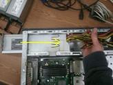
Now we can begin removing the power distribution board from the system. Unclip the connector from the back plane, and snake it through the chassis into the drive area out of the way. (See below, left)

Next, unclip the 2 white plastic straps located on the power supply cage.
(See below, center)

Remove power distribution board

Unclip straps on power supply cage
We can go ahead and unclip the main power connectors from the system board along with the ribbon cable, (See below, right) lift them out of the way for now.


Removing main power connectors from system board


This next step can be a bit tricky, unhook the 4 pin powerwire as well as the IDE cable from the cd-rom drive. Now remove the 2 screws that hold the dive in place and push it forward (you can remove it if you like) to give access to the 4 pin power wire on the 3.5” floppy drive. Unclip that wire and pull the wires off to the side with the rest of them.

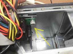
Here is a picture of the 4 pin wire for floppy drive below. Now it’s time to remove the power distribution board from the chassis. This is done by unscrewing the Phillips head at the top right of the board (pictured below).

Remove 4 pin wire cable

4 pin power wire for floppy

Once loosened, lift up on the board, pull back slightly, and continue pulling up till the board is out. The install of the non-redundant unit is basically the reverse of the removal, except you don’t have the ribbon wire from the redundant unit. Bundle the wires closely together and fish them through the back of the unit while sliding the power supply into place.

Remove Power Distribution Board
Bundle cables


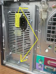
And then fasten the new unit to the back of the chassis as shown in the picture below, right:

Power Supply in PE1800 Case


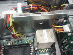
Once fastened, go through and run all the power connectors as they were with the power distribution board and it should look like the picture below, once finished. That is it!


Cables reattached without power distribution board


For a complete video How-to install, head over to http://youtu.be/7OV0DhScDc8 for this write-up and others. Don’t forget to check out our other videos at our YouTube channel: velocity783.

Have something you would like to know how to do? Or “will it work?” Then stop in to our website at: www.velocitytechsolutions.com in the video gallery and make a request!

Thursday, February 10, 2011

How do I upgrade the Memory on my Dell Poweredge R710 Server?

By Kay Winchell, Technical Support, Velocity Tech Solutions.
How do I upgrade the memory on my Dell Poweredge R710 Server? It seems to be the most frequently asked question lately for our sales and technical support staff. With the Nehalem processors controlling the memory of that unit, things can be a bit tricky compared to the previous generation of Dell servers. There is a whole new set of rules for adding memory, so let’s get started.
The biggest lesson to be learned, in my opinion, is not to skimp on the memory when purchasing the R710 server! Sometimes it haunts you in the long run when trying to upgrade later on, and this is one of the Dell servers where that is definitely true.
Let’s summarize some of the rules for this new architecture.
1. Memory for the R710 server is made in Un-registered dimms (UDimms) and Registered dimms (RDimms).
2. Memory is allowed to run at 800Mhz, 1066Mhz and 1333Mhz speeds.
3. There are up to 3 memory channels that are connected to each processor socket and up to 3 dimms per memory channel. A processor must be in the socket to use the channels.
4. UDimms come in 1 or 2GB stick sizes and are limited to 2 Dimms per memory channel.
5. RDimms come in capacities up to 8GB sticks. RDimms and UDimms cannot be mixed.
6. If the processor has a QPI Speed of 6.4GT/s the following applies:
a. 1 Dimm in each channel will run at 1333mhz (35GB/Sec.)
b. 2 Dimms in any channel drops the speed to 1066Mhz (32GB/Sec.), an 8.5% reduction in speed.
c. 3 Dimms in any channel drops the speed to 800Mhz (25GB/Sec.), a 28.5% reduction in speed.
7. Memory can be balanced (3 dimms across each channel), or unbalanced (less than 3 dimms across each channel). When your memory is unbalanced you will lose about 23% of bandwidth.

Here are some simple suggestions for getting the most out of your Poweredge R710.
o Start with a processor that supports 1333Mhz Memory.
o Use Rdimms.
o Keep the dimm sizes the same.
o Think in 3s.
Select the dimm size that gets you closest to the capacity you want, although you may not get the exact capacity you want.
I hope that answers some of your questions.
www.velocitytechsolutions.com

Thursday, January 13, 2011

Looking for hard drives for a Dell Power vault MD3000i??

You may be looking just a bit harder. If you didn’t purchase the Dell MD3000i and hard drives from Dell directly there are a couple of hard drives that are not able to be used in the Dell Power vault MD3000i.
Fujitsu SATA drives and all Maxtor drives are unsupported drives for that machine.
It seems Dell is moving more towards specific firmware for their drives (similar to HP). So in the event you purchase a newer Dell Powervault storage array or Dell Poweredge server make sure if you did not purchase the drives from Dell to check out the drivers and downloads section at Dell.com for the latest disk firmware.

Thursday, January 6, 2011

Need help installing an OS on your Dell server?

The easiest quickest way is to use Dell Systems Build and Update Utility.
This allows you to create a bootable DVD disk to boot the server to and allow you to install your server OS without the need to download drivers. Supports from Server 2003 R2 and up. Also Linux and ESX VMWare.


http://support.dell.com/support/downloads/download.aspx?c=us&cs=555&l=en&s=biz&releaseid=R288889&SystemID=PWE_2950&servicetag=&os=WNET&osl=en&deviceid=24134&devlib=0&typecnt=0&vercnt=3&catid=-1&impid=-1&formatcnt=0&libid=36&typeid=-1&dateid=-1&formatid=-1&source=-1&fileid=430015

Thursday, December 30, 2010

How to set up a Raid Array on a Dell Poweredge 2950 Server

The instructions below can also be used with the Dell Poweredge 1900, Dell poweredge 2900, and the Dell poweredge 1950, providing the PERC5i controller is used.
• When server is booting hit “Control R” when you see “Poweredge expandable Raid Controller Bios” to enter the RAID configuration utility.
• Under “VD Management tab” Hit “F2” to create a new “virtual drive”
• Hit “Enter” to choose the “RAID level” option
• Arrow down to choose the “RAID level” and hit “Enter” to accept
• Arrow down to “drives section” and hit “spacebar” to select the drives to be used. Hit “tab” after selecting the hard drives.
• The menu will then show the total size of the virtual drive. If this is correct then hit “tab” until you get to “VD Name” and name the virtual drive.
• Tab to advanced settings and set those if you choose or leave at defaults
• Tab to “OK” hit “enter to complete your new virtual drive.


**Best practices is to make sure all the hard drives are the same size and have the same Dell Part number

Friday, December 3, 2010

Dell Poweredge 1800 Power supplies- The Holy Grail of Power Supplies

Have a Dell Poweredge 1800 Server with a dying or dead power supply? First of all, let me send my condolences, and know that there is a solution or two.
The Poweredge 1800 server came with 2 versions of power supplies; redundant and non redundant. These “mini towers” were a great small business solution for financial and space purposes. As with most things, there is a time to be born, a time to die, a time to work and a time to panic.
It seems like the last 6 months of 2010 have seen a large number of Dell Poweredge 1800 power supplies fail. The first part of the year, it seems the Non Redundant Power supplies were hard to find and the redundant pretty common. Now they are both very hard to find, but it seems like the non redundant power supplies are a little easier to locate then the redundant.
So, is a new server not in your budget and your Dell Poweredge 1800 is down? There are options. You can convert each system. Example, if you have a PE1800 Server that has redundant power supplies, but you can’t find any replacement redundant power supplies, but can find non redundant power supplies you can remove the power distribution board and ribbon cables and install a non redundant power supply. Best practices always preaches that: redundancy is best, redundancy is best, redundancy is best, but in cases of late with this model of server, non redundancy may be your only option to limp you along until budgets loosen up or you’re so frustrated you take a sledge hammer and beat the PE1800.
It is also possible to convert the Non redundant power supply unit to a redundant unit. You just add a power distribution board and ribbon cables hook it up and you’re good to do.
Both types of power supplies are hard to come by, but if you find yourself down and needing one, I hope this helps.

Friday, November 12, 2010

Dell Poweredge Server Lineage

With the 10th Generation of the Dell Poweredge Servers out, the topic has come up about the Dell Poweredge Server family tree. There is really limited information even from Dell on the history of the Poweredge Server. I was hoping there would be a handy dandy document of evolution of servers complete with model number, years in production and all specs. Sadly, nothing comes that easy! I was able to find a list of model numbers from some helpful gentleman on Wikipedia so that was a start. Here is a list (not perfect but close) of all the Dell Poweredge Servers and the year of production.

As the years progressed, so did form factors. Towers are what started it all. Typically those older servers came in the 7U form factor and weighed about as much as a new Hummer.

Around the late 90s as more models came out they were all towers, but smaller sized towers. For example the Dell Poweredge 1300 would be say a mini tower by today’s standards and the Dell Poweredge 6350 would be a beastly 7U tower or the Hummer!

Right around the year 2001, servers became lighter in weight and the Dell Poweredge 1550 was welcomed with open arms to all techs that were suffering from sore backs.

In 2009, Dell exploded with many models of towers and rack mount servers along with a series of servers that featured the AMD Operton processors.

The “C Series” of Dell Poweredge Servers are starting to come out as of 2010.

If anyone has any other information, feel free to add or comment with correct information. I hope this is helpful to those that need it or to those that are just curious.


Dell Poweredge Model Number Year Produced (Approx)

Poweredge SP5100 1994
Poweredge SP5133 1995
Poweredge SP5133-2 1995
Poweredge 2100 1996
Poweredge 4100 1996
Poweredge 4200 1997
Poweredge 2200 1997
Poweredge 6100 1997
Poweredge 4300 1998
Poweredge 4350 1998
Poweredge 2300 1998
Poweredge 1300 1998
Poweredge 6300 1998
Poweredge 6350 1999
Poweredge 8450 1999
Poweredge 2400 1999
Poweredge 2450 2000
Poweredge 4400 2000
Poweredge 7150 2001
Poweredge 1550 2001
Poweredge 2550 2001
Poweredge 2450 2001
Poweredge 6400 2001
Poweredge 6450 2001
Poweredge 2500 2001
Poweredge 2550 2001
Poweredge 2500SC 2001
Poweredge 350 2001
Poweredge 500SC 2001
Poweredge 4600 2002
Poweredge 2650 2002
Poweredge 2600 2002
Poweredge 1400SC 2002
Poweredge 6650 2002
Poweredge 6600 2002
Poweredge 6650 2002
Poweredge 1750 2003
Poweredge 1655MC 2003
Poweredge 1650 2003
Poweredge 1600SC 2003
Poweredge 750 2004
Poweredge 700 2004
Poweredge 800 2005
Poweredge 2850 2005
Poweredge 830 2005
Poweredge 1800 2005
Poweredge 1850 2005
Poweredge 1855 2005
Poweredge 2800 2005
Poweredge 6800 2005
Poweredge 6850 2005
Poweredge 850 2005
Poewredge SC430 2005
Poweredge SC1420 2005
Poweredge SC1425 2005
Poweredge 860 2006
Poweredge SC440 2006
Poweredge SC1430 2006
Poweredge SC1435 2006
Poweredge 840 2007
Poweredge 1900 2007
Poweredge 1950 2007
Poweredge 2900 2007
Poweredge 1955 2007
Poweredge 2970 2007
Poweredge 6950 2007
Poweredge 2950 III 2008
Poweredge 1950 III 2008
Poweredge 2900III 2008
Poweredge T100 2009
Poweredge T105 2009
Poweredge T110 2009
Poweredge T300 2009
Poweredge T310 2009
Poweredge T410 2009
Poweredge T605 2009
Poweredge T610 2009
Poweredge T710 2009
Poweredge R200 2009
Poweredge R210 2009
Poweredge R300 2009
Poweredge R310 2009
Poweredge R410 2009
Poweredge R510 2009
Poweredge R610 2009
Poweredge R710 2009
Poweredge R805 2009
Poweredge R900 2009
Poweredge R905 2009
Poweredge R910 2009


Anne Tarantino (VelocityAnne)

Velocity Tech Solutions

www.velocitytechsolutions.com
Friday, November 5, 2010

Velocity Tech Solutions - How to replace a Dell PowerEdge 2850 backplane

Dell PERC Raid Controllers: What are they and what are the differences between each?

By Kay Winchell, CIO, Velocity Tech Solutions, www.velocitytechsolutions.com

“PERC” is a term used to describe the Dell PowerEdge Raid Controller family. PERC controllers are the interface between the operation system read/write instructions on the hard drives. These cards (for attaching storage to a server) or kits (for raid arrays internal to the server) have series levels from Perc2 to Perc6 and have been followed by the new H series. The various controllers have features that are mostly differentiated by type of connector, (PCI, PCI-E, SAS) raid levels supported, (Raid, 0,1,5,6,ect), the maximum level of hard drives supported, and whether they are internal kits or external cards.
The chart below describes first the internal (Integrated) Raid kits and secondly the external Raid Cards, the machines they are compatible with and the most common features known to us. Dell does have multiple part numbers for items that perform the same function, so we have not included the actual SKUs for the items. I have started with Perc 3 because the older Perc 2 cards are fairly rare now. Also, I have excluded some of the more uncommon raid controllers or controllers that are made for just one machine. The list below is not complete, please feel free to add or correct as necessary. Contact me if you have questions about what raid controller goes into your PowerEdge server.
The internal kits are usually composed of the Raid Key, the Raid Battery and the Raid (Cache) Memory dimm in the older servers. The key is typically installed on the mainboard of the server, while the battery and memory are usually found on the riser card. The newer servers usually just have an internal card that has the cache memory and a battery mounted on it.
The external card plugs into an expansion slot in the back of the machine and cables to a storage unit such as the Powervault or newer MD Series Enclosures or in some cases to a tape back up unit.

Internal Raid Controllers
Cache Memory Interface Max Drive
Controller Channel Machine Size Support Bus Raid Levels Support
Perc 3/si Single 2450 64mb SCSI U160 PCI Raid 0,1,5,10
Perc 3/di Dual 2550, 2650, 4600
128mb SCSI U160 PCI Raid 0,1,5,10
Perc 4/di Dual 2600
128mb SCSI PCI Raid 0,1,5,10,50 15
Perc 4e/si Single 1850
256mb SCSI PCI Raid 0,1,5,10,50 15
Perc 4e/di Dual 2800, 2850, 6800, 6850
256mb SCSI PCI Raid 0,1,5,10,50 15
Perc 5/i N/A 1900, 1950, 2900, 2950
256mb SAS/SATA PCI-E Raid 0,1,5,10,50 32
Perc 6/i N/A 1900, 1950, 2900, 2950
256mb SAS/SATA PCI-E Raid 0,1,5,6,10,50, 60 16
H700 to attach MD Storage 512mb & 1Gb Mini SAS PCI-E Raid 0,1,5,6,10,50, 60 16


External Raid Controllers
Interface Max Drive
Controller Channel Machine Cache Memory Support Bus Raid Levels Support
Perc 4/SC Single 1800, 1850, 2600, 2650, 4600, 1600SC,
64mb SCSI PCI Raid 0,1,5,10,50 40
600SC, 650, 700, 750, 800, 830, 850
Perc 4/DC Dual 1800, 1850, 2800, 2850
128mb SCSI PCI Raid 0,1,5,10,50 40
Perc 4e/DC
Dual 2800, 2850, 850
128mb SCSI PCI-E Raid 0,1,5,10,50 40
Perc 5E 1900, 1950, 2900, 2950, 2970, 6950
256mb SAS/SATA PCI-E Raid 0,1,5,10,50
R300, R805, R900, R905, T300

Perc 6E 1900, 1950, 2900, 2950, 2970, 6950 256 and 512 SAS/SATA PCI-E Raid 0,1,5,6,10,50, 60 144
R300, R805, R900, R905, T300

H800 to attach MD Storage 512mb & 1GB Mini SAS PCI-E Raid 0,1,5,6,10,50, 60 192

Monday, November 1, 2010

“I just got my server and it doesn’t work”

One of the most common questions we get here at Velocity Tech Solutions “I just got my server and it doesn’t work” or “my server just stopped working what do I do?” After that question there are typically a series of questions (with a little panic in the voice) “will I lose my raid”? “Is it the motherboard?” “I’m totally down, what am I going to do?”

There may be no need to panic it could be something simple.

Often times in shipping the server will take a bit of a beating. Many of them weigh 50 to 100lbs and the delivery drivers seem to loathe those poor packages more than the 3 oz boxes that can fit in their hands. There is also the reality that the delivery trucks don’t ride as smooth has a Cadillac. As a result of the server taking a rough ride both in the vehicle and via the loading process, the vibration of the rough ride can result in the memory, the processor, the riser or the controller card coming lose. Reseat each part in the server. Make sure each part is clipped in and secure.

The same can be true of a server that has been running constantly for a very long time. Servers pack a lot of power and over time the vibration can jolt some of the parts loose.

This may not be the only answer, but this is a starting point.

You can always call me, VelocityAnne at 888-784-2088 with any questions, anytime!

Friday, October 8, 2010

Different Generations of Dell Poweredge 1950 Server

The Dell Poweredge 1950, although one generation removed from the Dell line of Poweredge Servers, is still in high demand on the used market.

The 3 Generations of Poweredge 1950 series allows you to perform a myriad of duties in any modern data center. From application servers, to populating databases, from file servers to print servers, from mail services to collaboration services, the modern server is indeed to backbone of any modern business, be it large or small.

Below are the basics of each of the PE1950 server complete with generation. This can assist if your software calls for specific requirements. Again this doesn’t drill down to every bit of difference between the generations, but a guideline.

Dell PE1950 1U Gen I

Processors: Up to 2, Intel Dual Core processors; Max processor speed is 3.73, max cache is 4m, max front side bus is 1333Mhz.

Memory: Up to 32gb 667Mhz

I/O Slots: three expansion slots; 2 x 64-bit PCI-X; 1 x PCI Express x8.

Drive Controllers: Embedded PERC integrated PCI SAS controller.

Raid Controllers: Embedded PERC 5/i, PERC4e/Di (single channel RAID with 256MB of battery-backup cache)

Drive Bays: 4, 2.5” or 2, 3.5” SAS or SATA Hard drives

Power supplies: 750W hot-plug/redundant.

Dell PE1950 1U Gen II

Processors: Up to 2, Intel Dual Core processors; Max processor speed is 3.0, max cache is 8m, max front side bus is 1333Mhz.

Memory: Up to 32gb 667Mhz

I/O Slots: three expansion slots; 2 x 64-bit PCI-X; 1 x PCI Express x8.

Drive Controllers: Embedded PERC integrated PCI SAS controller.

Raid Controllers: Embedded PERC 5/i, PERC4e/Di (single channel RAID with 256MB of battery-backup cache)

Drive Bays: 4, 2.5” or 2, 3.5” SAS or SATA Hard drives

Power supplies: 750W hot-plug/redundant.

Dell PE1950 1U Gen III

Processors: Up to 2, Intel Dual Core processors; Max processor speed is 3.0, max cache is 12m, max front side bus is 1333Mhz.

Memory: Up to 64gb 667Mhz

I/O Slots: three expansion slots; 2 x 64-bit PCI-X; 1 x PCI Express x8.

Drive Controllers: Embedded PERC integrated PCI SAS controller.

Raid Controllers: Embedded PERC 5/i, PERC4e/Di (single channel RAID with 256MB of battery-backup cache)

Drive Bays: 4, 2.5” or 2, 3.5” SAS or SATA Hard drives

Power supplies: 750W hot-plug/redundant.

About velocityanne
Charming and personable sales GURU for Velocity Tech Solutions. We are the BEST source for Dell Poweredge and HP Proliant servers and server parts.
View all posts by velocityanne →

Thursday, October 7, 2010

Types of Raid and the Advantages of Each

I thought I’d let our head Geek write more words of her server wisdom. We get so many questions around setting up raid on Dell Poweredge Servers that we thought this would be an easy way to help.

What are the types of Raid and the advantages of each?

By Kay Winchell, Velocity Tech Solutions, www.velocitytechsolutions.com

A vitally important function of the network administrator is to protect and secure the data of a business. An equally important function is maximizing the performance of the network. A cost effective way of both protecting data and maintaining access to the network is to install a RAID array on your server’s hard drives. RAID, or Redundant Array of Independent Disks, is what we use to describe a data storage method that can manage data among multiple hard disk drives on a server . The main reason a Raid Array is used is for performance and redundancy, the benefits of which depend on the type of Raid chosen.

The most common types of Raid Arrays for servers are Raid 0, Raid 1, and Raid 5, 6, 10, 50 and 60. We will discuss the trade-offs between performance (speed of access) and redundancy (protection of data) with each type of RAID.

Raid 0, which is also called Striping, provides for highest performance and zero redundancy. The Raid controller writes data across all drives in the array and reads and writes to multiple disks at the same time. Speed is enhanced, however, if one hard drive in the array fails, total data loss occurs. A business will usually use Raid 0 when speedy temporary access to large capacity disk space is needed, and in the case of disk failure the data can be easily reloaded from another source without impacting the business. 100% of the disk space is available for use with a RAID 0 configuration, so the cost of storage is the lowest. To summarize this option, speed is high, disk storage cost is the lowest, and safety of the data is lowest.

Raid 1, which is also called Mirroring, provides for high redundancy, but zero increase in performance. Each hard drive is paired with another, one being a complete copy, or mirror, of the other. If one hard drive fails, the paired drive contains the same data. To set up Raid 1, the server must have at least two hard drives. Businesses will usually use a RAID 1 when absolute data safety and access are required. However, cost of disk storage is a secondary consideration, as only 50% of the disk space is actually available. To summarize this option, speed is medium, disk storage cost is the highest, and data safety is high.

Raid 5, which is also called Stripe Sets with Parity, has a mix of performance, storage cost, and redundancy benefits. Data is written to all of the drives in the array and parity data is written to all of the drives in the array as well. The result does not require disk duplication like mirroring but does maintain redundancy. If a hard drive in the array fails, a new drive can be added and the array repairs itself while the system continues to operate normally. For this reason, Raid 5 is the array of choice for most servers with three or more disks. The RAID parity requires one drive per RAID set, so disk availability is always one hard drive less than the number of drives in the array, still much better than the 50% capacity of mirroring.

Raid 6, which is also called Stripe Sets with Dual Parity, is designed to improve the disk failure tolerance of RAID 5 by withstanding the failure of two drives in the array. Raid 6 functions like Raid 5, with stripe sets and parity, but adds a second parity scheme that distributes data across different disks than the first parity scheme to enable dual parity. Raid 6 requires a minimum of 4 disks and the parity requires two hard drives per RAID set. Raid 6 is a particularly good option for servers that use SATA drives, which are less expensive, but also less reliable, and may possibly require the ability to withstand a double disk failure.

Raid 10, which is also called Stripe Sets and Mirroring, is a multiple array set that combines Raid 0 Striping and Raid 1 Mirroring. The base level is two or more Raid 1 arrays, which as you will recall, is an array where each drive has an exact duplicate of itself. The second level is a Raid 0 array which stripes all of the data from the sub-arrays across all of the drives in its array. So, there is mirror redundancy in the sub-array and no redundancy in the main array. This provides for speed of access and combined capacity in the main array. One drive can fail in each sub-array and still be recoverable. Like mirroring, only 50% of the total drive capacity is available, but both redundancy and performance are enhanced by this Raid method.

Raid 50, which is also called Stripe Sets, is another multiple array set that combines Raid 5 with Raid 0. The base level is two or more Raid 5 arrays, which as you will recall, uses stripes and parity to maintain redundancy. The second level is a Raid 0 array which stripes all of the data from the sub-arrays across all of the drives in its array. So, there is parity redundancy in the sub-array and no redundancy in the main array. This provides for speed of access and combined capacity in the main array. One drive can fail in each sub-array and still be recoverable. However, like the difference between Raid 1 and Raid 5, the total disk capacity is increased because parity uses only one drive per array, as opposed to mirroring, which uses one drive out of each two.

Raid 60, which is also called Stripe Sets and Dual Parity Stripe Sets, is another multiple array set that combines Raid 6 with Raid 0. The base level is two or more Raid 6 arrays, which as you will recall, uses dual parity stripe sets to maintain redundancy. The second level is again a Raid 0 array, which stripes all of the data from the sub-arrays across all of the drives in its array. So, there is dual parity redundancy in the sub-array, and no redundancy in the main array. Again, this provides for speed of access and combined capacity in the main array. Two drives can fail in each sub-array and still be recoverable. Total disk capacity is still increased over mirroring, while preserving redundancy.

Your server, depending on its age, may not be capable of installing the newer types of Raid array.