Search This Blog

Tuesday, August 9, 2011

Replacing Raid Kit in Dell PowerEdge 2850

By Mike Kidd – Velocity Tech Solutions
We have all been there, “memory/battery error” on the PowerEdge 2800-2850-1850 server. And most of the time this can be fixed rather easily with minimal downtime. So today, I will be doing a walk-through on replacing the raid kit on the 28xx series server. Now there are a few cases where it can end up being the riser card causing the issue, but replacing the raid kit seems to fix it more often than not.
Fig 1
First things first, Power down your server and remove the cover. You will now be looking at the picture shown in Fig 1. The yellow circles show the location of the raid kit components (memory, battery, raid key).

Fig 2
While you can get at the riser memory and the raid key without removing anything from the server, it will make your life a whole lot easier to take out or at least lift up the entire riser itself to get at the battery clip. Fig 2 shows the location of the release lever for the riser.
It is a blue lever towards the back of the server on the left side if you are facing the front of the server. Pull the lever back towards you. Be careful however, because sometimes it can bind while releasing and snap the pins inside causing you to have very bad day.

Once you have the lever lifted you can lift the riser straight up and off to the side to give you access to the clip that holds the battery wire to the riser card. Press in and lift to release the battery clip. Fig 3 shows the location of the battery clip and release tabs for the riser memory.

Fig 3
The hardest part of this removal is the battery from its carrier. There is a blue plastic tab (Fig 4) for you to pull up on while pressing back the black plastic that holds it in place.

Fig 4
Now that you have the entire raid kit removed, the installation of the new one is just the reverse of the removal.

For a more detailed and in-depth tutorial of this procedure, check out our How-to video at:  http://www.youtube.com/watch?v=kClQrK4-Crc. Don’t forget to check out our other videos at our YouTube channel: velocity783.

Have a How-To request?  Request your own and we will get right to work on it for you!

Tuesday, June 21, 2011

Setting up a Raid 5 with Perc 5/6 Raid Controllers

By Mike Kidd - Velocity Tech Solutions

For this edition of Tech Corner, I will be explaining how to set up a raid 5 on your Dell server with a Perc 5/6 raid controller. For the purpose of this demonstration, I will only be using 3 drives (the bare minimum required) for my raid 5 setup. Also, if your server is presently in production (live and in use) I don’t advise setting this up without consulting Dell to prevent data loss.

Figure 1


First thing we are going to do is start up our server, and when the screen displays Fig 1 press CTRL+R, and you will be presented with a menu that looks like Fig 2.

Figure 2


Once at this menu your screen will, assuming you do not already have a virtual disk setup, look like this. Now press F2 and a menu will pop up like the one in Fig 3.

Figure 3


Hit enter on “create new VD”, now you see a screen like Fig 4.

Figure 4


Hit “Enter” on “raid level” and a drop box will appear giving you available raid levels. Select “raid 5” and hit “enter”, press “Tab” and the cursor box will drop down to your available hard drives. Select these drives by pressing the “space bar”. Note you will see each drive ID appears on the right and a selected drive indicator on the left as an “X”. Now you can press “TAB” to move the cursor to your VD size and VD name, and advanced options.

For ease of use and my demonstration, just TAB over to the “OK” box on the far right of your screen and press “enter”. A message box will appear advising you to initialize your new Virtual Disk, which is exactly what we are going to do now. Once you press enter and the message box closes you will be back at the screen shown in Fig 2, except now you will actually see a virtual disk. Press F2 on your new VD and a menu will appear like that in Fig 5.

Figure 5


Select “Initialization” and press “enter”. Scroll down to “Fast Init.” And press “enter”. A Prompt will appear warning you that by initializing your new VD it will destroy any data on the drives. So as I said in the beginning, if your server is in production and is live and in use, PLEASE consult dell before continuing. Heeding my warning, Press enter and you will see a progress bar quick flash over your VD and say it is complete. A full initialize takes a very long time, so this at least allows you to install an OS or at least use the drives till the full initialize has completed. That’s it! You’re done!

For a more detailed and in-depth tutorial of this procedure, check out our How-to video at: http://www.youtube.com/watch?v=044qCZNiUJE. Don't forget to check out our other videos at our YouTube channel: velocity783.

Have a How-To request? Request your own and we will get right to work on it for you!

Monday, May 23, 2011

How to Change a 4 Bay Backplane to a 6 Bay Backplane on a Dell Poweredge 2950

By Mike Kidd

You know the old saying; if it isn’t broke don’t fix it? This is certainly true with the PowerEdge 2950 server. However, if you are one of those that has the 4 bay backplane installed you would probably enjoy more storage space. Fear not, there is a 6 bay backplane that is fairly easy to swap into your server and give you that expandability you want. So in light of that, I will be showing you a step by step on how to do this.

Things you will need.

Things you will need for the conversion:
  • 6 bay backplane
  • Flat-head screwdriver
  • Second cable for raid controller
All of the parts needed are available on our website www.velocitytechsolutions.com

First, shut down your server and remove your hard drives from the server, careful to note the order and placement of them for when you go to re-install them. You do not necessarily have to remove them completely from the server; you can just back them out to release them from the backplane.

Lightly pry the blue release lever
away from the riser card
Now, remove the cover from the server and proceed to remove your raid controller from the server. Sometimes they are stubborn and you need to take your flat-head screwdriver and lightly pry the blue release lever shown in the picture to the left, away from the riser card. Now, remove the black plastic shroud that is above the ram and processors and unhook the cable for the CD/DVD ROM drive.
Unhook the display cable from
the side riser by pressing the
metal tabs on each side.

Next, unhook the display cable from the side riser by pressing the metal tabs on each side, shown to the right. This connector can be stubborn as well and may require our trusty flat-head to lightly pry up one side to break it free.

Unhook the 2 power connectors..
At this point, remove the side riser by pressing in the 2 blue tabs and lifting upwards on the card. Go ahead and unhook the 2 power connectors for the backplane, shown in the picture to the left, as well as unhooking the power cord from the CD/DVD ROM drive. I personally like to slide the CD/DVD ROM drive forward a bit, but user preference.
Take out the 4 cooling fans by
lifting up on the orange
release bar.


Take out the 4 cooling fans by lifting up on the orange release bar.

Now, take out the black plastic piece that the fans were sitting on by pressing down on the blue lever, shown in the picture below, and by lifting up and out on the black plastic piece.

Take out the black plastic piece...
by pressing down on the blue lever.
Pull back on the blue release tab, shown in the picture on the right, and lift up on the backplane. While it is up, push towards the back of the server to clear the mount fins and the backplane now should be free to set off to the side.

Pull back on the blue release
tab and lift up on the backplane.
We can now do the reverse of the removal for installing the 6 bay backplane. Install it facing in the direction, show in the bottom left picture.

Install the 6 bay backplane facing in the
direction shown in this picture.
Line up the mount fins on the chassis to the backplane, and simply slide the unit down. It will lock in place. Install your riser card and plastic fan mount assembly next, then your raid controller, fans and power cables. Then, re-connect your CD/DVD ROM drive and place the plastic fan shroud in place and put the cover for the server back on.
Ensure controller 1 cable is
connected.


You are DONE! Now, you can re-install your drive and add another 2 hard drives for storage or whatever your heart desires.


For a more detailed and in-depth tutorial of this procedure, check out our How-to video at:  http://youtube.com/watch?v=T-oCuNbm-P0. Don't forget to check out our other videos at our YouTube channel: velocity783.

Have a How-To request?  Let us know and we will make a video for you!

Monday, April 18, 2011

Changing Out a Redundant Power Supply to Non-Redundant in a PowerEdge 1800 Server

Our Newest and Geekiest tech, Mike (the kid) Kidd, wrote this step-by-step article on changing a Dell Poweredge 1800 server from a redundant power supply set up to a non redundant power supply set up. Since the redundant power supplies are very difficult to get, this is a great solution to a big problem.

By Mike Kidd

As technology gets a little older, parts become increasingly hard to find and purchase. A true testament of this would be the redundant power supplies for the Dell Poweredge 1800 server. Even we are having a hard time getting a hold of these little guys. However, you are in luck! There is an alternative to redundant power supplies for the 1800, and this is the Non-redundant unit. So today I will be showing you how to change out your redundant unit with the Non. It may seem like a challenging job, but you will see that it is not that hard and does not take very long to complete, and hey, saving money is good too!


Removing Power Supply from Server

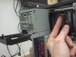
Begin by powering down and unhooking everything from your server. Then, remove the 2 redundant power supplies from the tower. There will be little black tabs on the back of them (pictured left) that you need to “pinch” up, and pull down. The unit will pull out. Now, remove the bezel, tip your case on its side, and remove the side panel. The next step will be to remove the big black fan shroud from the case.

Removing Black fan


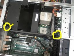
There are 2 tabs on the top of the shroud, closest to you (pictured right). Press them both down, while lifting the entire assembly upwards. But do not lift too far; there is still a power wire for the fan attached to the system board. Unhook that wire and set the shroud off to the side.

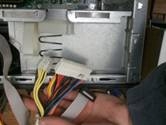
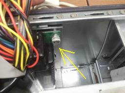
Now we can begin removing the power distribution board from the system. Unclip the connector from the back plane, and snake it through the chassis into the drive area out of the way. (See below, left)

Next, unclip the 2 white plastic straps located on the power supply cage.
(See below, center)

Remove power distribution board

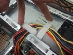
Unclip straps on power supply cage
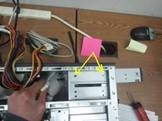
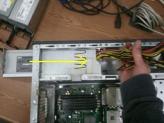
We can go ahead and unclip the main power connectors from the system board along with the ribbon cable, (See below, right) lift them out of the way for now.


Removing main power connectors from system board


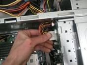
This next step can be a bit tricky, unhook the 4 pin powerwire as well as the IDE cable from the cd-rom drive. Now remove the 2 screws that hold the dive in place and push it forward (you can remove it if you like) to give access to the 4 pin power wire on the 3.5” floppy drive. Unclip that wire and pull the wires off to the side with the rest of them.

Here is a picture of the 4 pin wire for floppy drive below. Now it’s time to remove the power distribution board from the chassis. This is done by unscrewing the Phillips head at the top right of the board (pictured below).

Remove 4 pin wire cable

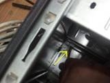
4 pin power wire for floppy

Once loosened, lift up on the board, pull back slightly, and continue pulling up till the board is out. The install of the non-redundant unit is basically the reverse of the removal, except you don’t have the ribbon wire from the redundant unit. Bundle the wires closely together and fish them through the back of the unit while sliding the power supply into place.

Remove Power Distribution Board
Bundle cables


And then fasten the new unit to the back of the chassis as shown in the picture below, right:

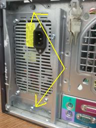
Power Supply in PE1800 Case


Once fastened, go through and run all the power connectors as they were with the power distribution board and it should look like the picture below, once finished. That is it!


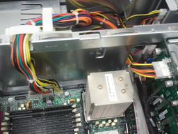
Cables reattached without power distribution board


For a complete video How-to install, head over to http://youtu.be/7OV0DhScDc8 for this write-up and others. Don’t forget to check out our other videos at our YouTube channel: velocity783.

Have something you would like to know how to do? Or “will it work?” Then stop in to our website at: www.velocitytechsolutions.com in the video gallery and make a request!

Thursday, February 10, 2011

How do I upgrade the Memory on my Dell Poweredge R710 Server?

By Kay Winchell, Technical Support, Velocity Tech Solutions.
How do I upgrade the memory on my Dell Poweredge R710 Server? It seems to be the most frequently asked question lately for our sales and technical support staff. With the Nehalem processors controlling the memory of that unit, things can be a bit tricky compared to the previous generation of Dell servers. There is a whole new set of rules for adding memory, so let’s get started.
The biggest lesson to be learned, in my opinion, is not to skimp on the memory when purchasing the R710 server! Sometimes it haunts you in the long run when trying to upgrade later on, and this is one of the Dell servers where that is definitely true.
Let’s summarize some of the rules for this new architecture.
1. Memory for the R710 server is made in Un-registered dimms (UDimms) and Registered dimms (RDimms).
2. Memory is allowed to run at 800Mhz, 1066Mhz and 1333Mhz speeds.
3. There are up to 3 memory channels that are connected to each processor socket and up to 3 dimms per memory channel. A processor must be in the socket to use the channels.
4. UDimms come in 1 or 2GB stick sizes and are limited to 2 Dimms per memory channel.
5. RDimms come in capacities up to 8GB sticks. RDimms and UDimms cannot be mixed.
6. If the processor has a QPI Speed of 6.4GT/s the following applies:
a. 1 Dimm in each channel will run at 1333mhz (35GB/Sec.)
b. 2 Dimms in any channel drops the speed to 1066Mhz (32GB/Sec.), an 8.5% reduction in speed.
c. 3 Dimms in any channel drops the speed to 800Mhz (25GB/Sec.), a 28.5% reduction in speed.
7. Memory can be balanced (3 dimms across each channel), or unbalanced (less than 3 dimms across each channel). When your memory is unbalanced you will lose about 23% of bandwidth.

Here are some simple suggestions for getting the most out of your Poweredge R710.
o Start with a processor that supports 1333Mhz Memory.
o Use Rdimms.
o Keep the dimm sizes the same.
o Think in 3s.
Select the dimm size that gets you closest to the capacity you want, although you may not get the exact capacity you want.
I hope that answers some of your questions.
www.velocitytechsolutions.com

Thursday, January 13, 2011

Looking for hard drives for a Dell Power vault MD3000i??

You may be looking just a bit harder. If you didn’t purchase the Dell MD3000i and hard drives from Dell directly there are a couple of hard drives that are not able to be used in the Dell Power vault MD3000i.
Fujitsu SATA drives and all Maxtor drives are unsupported drives for that machine.
It seems Dell is moving more towards specific firmware for their drives (similar to HP). So in the event you purchase a newer Dell Powervault storage array or Dell Poweredge server make sure if you did not purchase the drives from Dell to check out the drivers and downloads section at Dell.com for the latest disk firmware.

Thursday, January 6, 2011

Need help installing an OS on your Dell server?

The easiest quickest way is to use Dell Systems Build and Update Utility.
This allows you to create a bootable DVD disk to boot the server to and allow you to install your server OS without the need to download drivers. Supports from Server 2003 R2 and up. Also Linux and ESX VMWare.


http://support.dell.com/support/downloads/download.aspx?c=us&cs=555&l=en&s=biz&releaseid=R288889&SystemID=PWE_2950&servicetag=&os=WNET&osl=en&deviceid=24134&devlib=0&typecnt=0&vercnt=3&catid=-1&impid=-1&formatcnt=0&libid=36&typeid=-1&dateid=-1&formatid=-1&source=-1&fileid=430015